Mechatronics | Systems design | Solidworks | Arduino
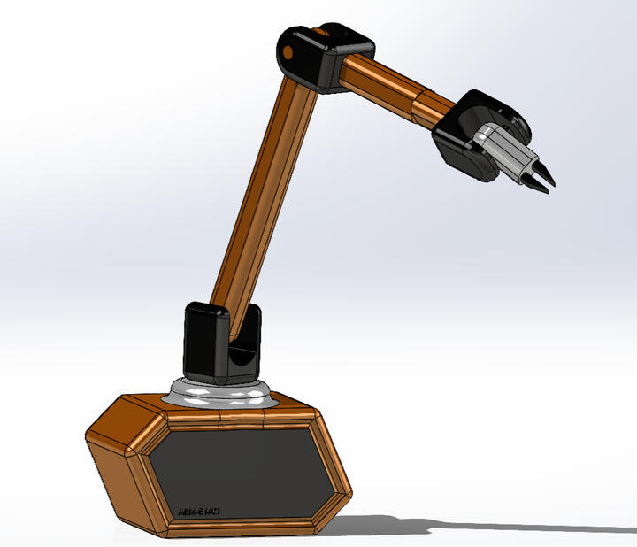
ARM-E: 6 DOF Robot Arm
I am currently designing a 6 DOF robot arm. ARM-E's first mission is to stack blocks, he will achieve this goal through careful design, engineering, and Arduino code. Stepper motors and servos will be controlled in a 3D printed housing. The initial prototype to the right was modeled in Solidworks to base inverse kinematic equations upon and to serve as a proof of concept. Individual components will be further refined. The end goal is to use ARM-E to assist with household tasks and eventually be used in conjunction with a surgical instrument.
(Dec 2023 - Present)
Design Approach
This project is executed using a modular design approach. The wider system consists of a base, shoulder, bicep, elbow, forearm, wrist, and gripper.
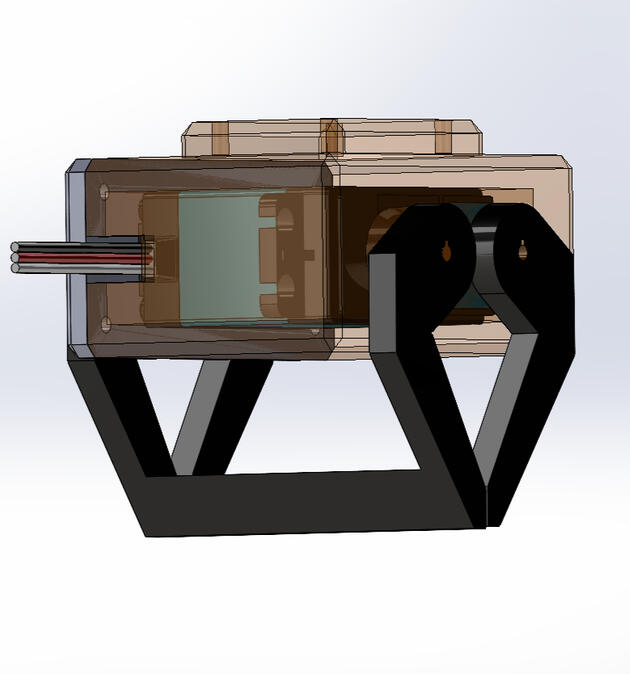
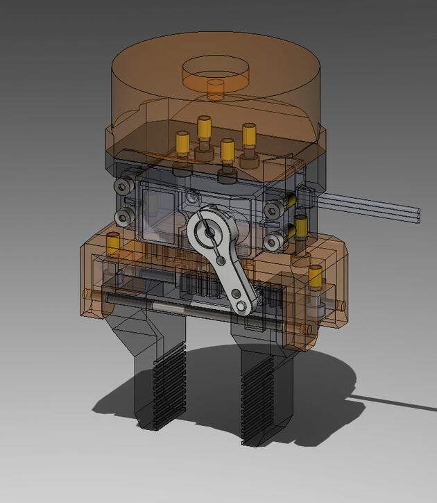
Gripper V1
The gripper is the first module being designed. Pictured above was the first prototype. This design was not chosen due to complexity, it required three bearings and shafts.
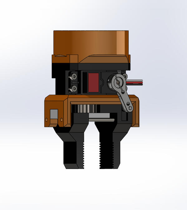
Gripper V2
This is the second and current gripper design, it operates using a rack and pinion between the jaws of the gripper. This design is favored for its simplicity.
DFA Decisions
Heat set inserts selected to allow parts to be mechanically linked. Metal insert preferable to printing threads since plastic threads will strip over time.
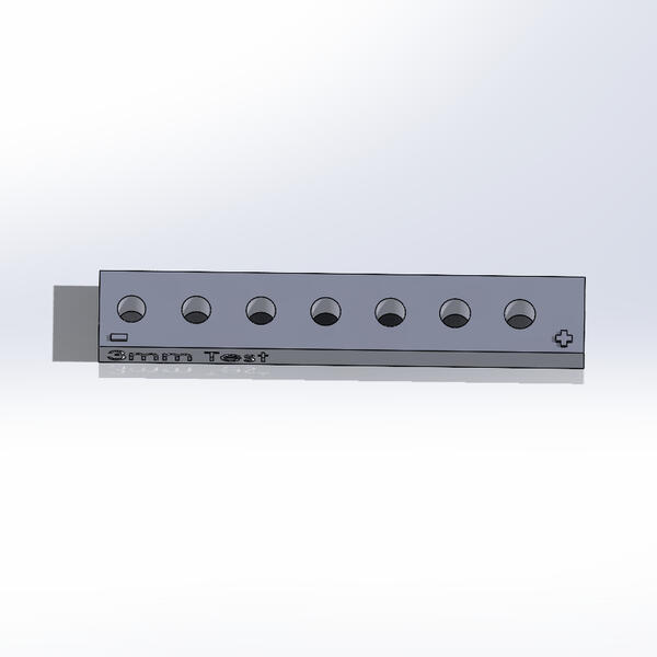
DFM Desicions
Three hole test strips were created and printed to test hole diameters variation during printing. Hole sizes will be adjusted larger in CAD, (ex. 3.5mm for a 3mm hole).
Full Assembly
Modeled all screws and inserts in Solidworks and assembled the module to test fits and clearances. Holes will be modified based on test hole strip results.
Disassembly
Assembly
Initial testing proved jaws could move but they got stuck on the rails. Jaws were moving tangent to the pinion without restraints.
The gear housing was redesigned to enclose the jaws and restrict their motion to one axis. Updated travel distance in code.
Groove in the jaw that the servo arm sits in was also made deeper to ensure it would not slip out. The updated parts allowed for picking.
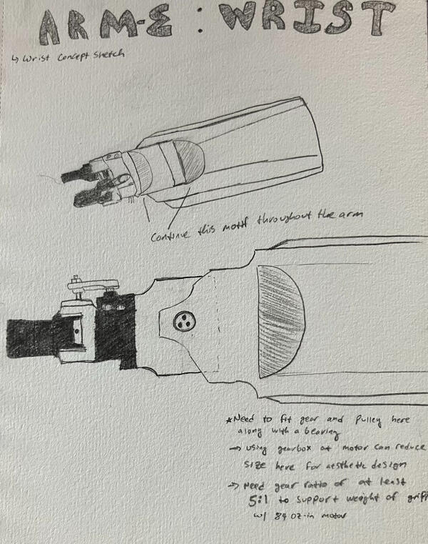
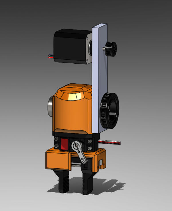
Wrist Concept Design
I plan to use a timing belt to drive the wrist joint with a stepper motor that will be mounted further towards the elbow to reduce torque required from the motor. Sketching allows me to get design ideas out of my head - this helps me to have before jumping to CAD.